Total station search
Hydraulic pressSteel tube hydrostatic testing machineSteel pipe hydraulic press
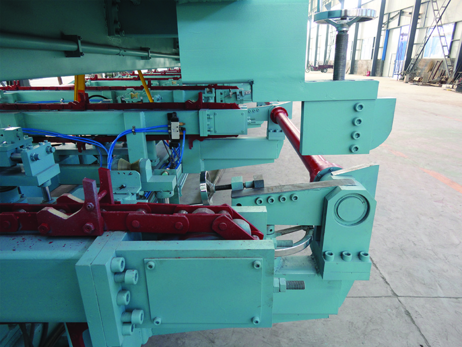
The steel pipe hydraulic press is an important equipment in the production process of steel pipes. In the previous pipe production line,after the hydraulic pressure of thesteel pipe hydraulic press was finished, one end of the steel pipe was stuck in the fixed end sealing ring, and the steel pipe could not be disengaged. It is to let the moving end quickly move the equipment up and down a few times, swing the steel pipe up and down a few times, and slowly pull it out of the sealing ring at the fixed end to send the disengaged steel pipe and carry out the suppression operation of the next steel pipe. The above methods are messy in operation, occupying a lot of time, there are hidden safety hazards, and severe restrictions on power production. The author summed up the experience through field debugging and designed a steel pipe clamping and concession equipment, which solved the problem that the steel pipe could not be detached when it was stuck in the sealing ring after the hydraulic pressure was applied.
The steel pipe clamping concession device consists of a lower clamping device and an upper clamping device, which are respectively connected to the guide rails fixed on the upper and lower force beams. The upper clamping device and the lower clamping device are driven by 4 oil cylinders fixed on the upper and lower force beams. The scale of the moving distance is 0 ~ 200mm, the steel pipe is pulled out from the sealing ring at the fixed end, and the steel pipe is smoothly sent out.
The steel pipe clamping and concession equipment adopts V-shaped upper and lower clamping blocks that can satisfy different specifications of steel pipes. It has a wide range of applications, reasonable structure, stable and reliable operation functions, simple operation, and improved production power.
The steel pipe clamping concession device is composed of an upper clamping device 10 and a lower clamping device 12. The lower clamping device 12 is placed on the guide rail of the pull - down force beam 16 of thehydraulic test machine , and the upper clamping device 10 and the pull beam of the hydraulic test machine The guide rails of 11 are connected, the top hydraulic cylinder 14 and the second hydraulic cylinder 21 are fixed on the pull-down beam 16, and the third hydraulic cylinder 6 and the fourth hydraulic cylinder 18 are fixed on the pull-up beam 11.

The lower clamping device 12 includes a fixed bracket 3, a roller group 22, a movable frame 15, a lower clamping block 1, a guide rod 7, and a rear axle seat 20. The fixed bracket 3 is provided with a roller group 22 and a movable frame 15 ; The upper frame of the movable frame 15 has a lower clamping block 1, and a top hydraulic cylinder 14 and a guide rod 13 are arranged under the movable frame 15.
The primary effect of the roller set 22 is that when the second hydraulic cylinder 21 is extended, it can move on the pull-down force beam 16 to reduce the friction to complete the movement of the lower clamping equipment; the movable frame 15 is used for the equipment clamping block 1 and raised The first effect of the top hydraulic cylinder 14 and the guide rod 4 is to lift the steel pipe, the center line of the steel pipe is common with the center line of the steel pipe hydraulic press, and the steel pipe is clamped together with the upper clamp.
The rear axle seat 20 is connected with the pull-down force beam 16 and the second hydraulic cylinder 21.
The upper clamping device 10 includes a guide rail 4, a support base 5, a movable frame 8, an upper clamping block 9, a guide rod 7, a rear axle seat 20, and a connecting piece 19. The guide rail 4 is connected to the upper tension beam 11. The guide rail 4 is provided with a support base 5. The support base 5 moves on the guide rail 4. The support base 5 is provided with a movable frame 8, an upper clamping block 9, a guide rod 7, and a third hydraulic cylinder 6.
The primary effect of the support seat 5 is that the center line of the steel pipe is the same as the center line of the steel pipe hydraulic press and clamps the steel pipe together with the lower clamp; the rear axle seat 20 is connected with the upper tension beam 11 and the fourth hydraulic cylinder 18.